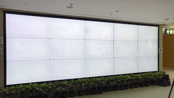
Why frames splice at all
A one-piece 110-inch frame cannot travel in a lift, survive a corridor corner, or be replaced by two technicians without drama. So large frames in this catalogue's programme — standard product to 98 inches on the large format line, the programme supplier-specified to 500 inches — are built as profile segments that join on site into one continuous sensing perimeter. The catalogue even lists a dedicated splicing touch frame and a 93-inch DIY frame positioned for video wall work; splicing is a product category here, not an improvisation. The video wall page covers when a wall should be spliced at all.
The joint is the whole game
At a segment joint, two profiles meet and their emitter/receiver arrays must continue the grid without a dead band or a double-counted stripe. Mechanically this is a tolerance problem measured in tenths of millimetres across metres of aluminium — which is why large frames are installed against the wall's own reference, not against the previous segment's optimism. Temperature is the silent variable: a 4-metre aluminium perimeter grows measurably between a cold morning install and a sun-warmed afternoon, and joint design must absorb the movement without opening the grid. When you evaluate a large-frame quotation, ask how joints are located and locked; the answer separates frame engineering from frame assembly.
Wall flatness: the specification nobody owns
The infrared field is a plane. The wall is a suggestion. A wall that bows by a centimetre across its diagonal puts the sensing plane in a fight with the glass line, and the symptoms — dead patches near the bow, eager touches near the crown — look exactly like sensor faults while being pure geometry. Commissioning a large frame therefore starts with a straightedge on the wall, not with the frame: shim the mounting line true, then hang the frame. On video walls, the panel array's own flatness enters the same ledger. This is unglamorous, billable, essential work, and it is why large-frame projects are quoted from drawings and site facts rather than from a shopping cart.
Calibration across segments
Calibration maps the physical field to the pixel space, segment by segment, then verifies continuity across joints with slow diagonal drags — the drag is the audit: any step, doubling or hesitation at a joint line is visible immediately. Multi-PC walls add a mapping question (one host spanning outputs, or several hosts dividing the wall) that must be settled before calibration, since the coordinate space belongs to the host layout. The general calibration discipline is in the installation guide; the large-format delta is simply that calibration is a procedure with witnesses and a sign-off, not a wizard you click through.
Service reality
The spliced architecture pays its second dividend in service: a damaged segment or PCBA is swapped without disturbing the wall, from the components programme. Design the install so segments are individually reachable — a frame entombed behind fixed joinery converts a one-hour swap into a demolition. Large touch done well is indistinguishable from magic for its users and from carpentry for its maintainers; plan for both audiences.
Acceptance testing: proving the wall before you praise it
A large frame should be accepted the way a lift is accepted — by test, not by impression. The acceptance protocol we recommend has four passes. The grid pass: a test pattern of points across the full field, each touched and recorded; any dead or doubled point localises its segment immediately. The drag pass: slow diagonals corner to corner, watching for steps at segment joints and hesitation at the field's centre; the drag is merciless and reveals in seconds what a demo hides. The crowd pass: the specified number of simultaneous users performing the real application's gestures at real content — multi-touch claims are only meaningful at the application's own targets. The soak pass: the wall left live through a full day of the room's lighting and temperature cycle, because joints and electronics both have thermal opinions. Record all four passes in the commissioning document with the calibration file's version. This protocol converts "it seemed fine" into evidence — for the client accepting the wall, for the integrator defending the work, and for the service team who will thank both when a segment is swapped in year three and the new calibration can be compared against the original. Large touch is construction; construction ends with inspection, not applause.
Documenting a spliced wall for its second decade
A spliced wall will outlive its installers' memory of it, so its documentation is a deliverable equal to the hardware. The commissioning pack should contain: the wall drawing with segment numbering as installed (not as planned — they differ, and the difference is the pack's value); the calibration file and the acceptance records from the four-pass protocol; the host mapping that assigns coordinate space to outputs; the thermal note recording the room conditions during calibration; and the service map showing which segments are reachable without dismantling neighbours. File it where facilities actually look — with the building's systems documentation, not in the integrator's project folder. Future interventions then begin from evidence: when a corner drifts in year four, the technician compares against the acceptance grid and learns in an hour whether the wall moved, a segment aged, or the content changed. Walls documented this way get maintained; walls that live in one installer's head get replaced early and blamed unfairly. The frame programme's segment architecture makes the wall serviceable in principle; the documentation is what makes it serviceable in fact.
Choosing the team for a spliced install
Finally, a procurement note disguised as engineering: spliced walls should be installed by whoever will document them. Ask bidders to show a previous commissioning pack — anonymised is fine — and judge the pack, not the pitch. A team that produces grid-pass records, calibration files and a segment map as routine artefacts will produce a good wall; a team that describes calibration as "the laptop sorts it out" will produce a wall that performs beautifully until its first thermal cycle. The hardware in this catalogue is specified for the regime; the install team's paperwork is how you know the regime will be respected on your wall, on your site, on the day. Buy the paperwork as deliberately as the profiles.
A short glossary for the specification meeting
Three terms recur in large-frame conversations and are worth fixing before money is discussed. Dead band: a strip of the field where touch is not sensed — at a healthy joint, there is none; the drag pass exists to prove it. Segment mapping: the assignment of each physical profile segment to its span of the coordinate space, held in the calibration configuration; remapping is a commissioning act, not a user setting. Field flatness: the deviation of the installed sensing plane from true, the sum of wall, mounting and profile tolerances — the number the straightedge measures and the shims correct. With those three terms shared, a specification meeting between client, integrator and manufacturer stays in one language, and the wall that results tends to deserve the confidence placed in it.